
Alexander Shchapov


As the time passes I’m losing hope for getting my parcel with bullet connectors. It’s been already more than 20 days since it was shipped from Netherlands and it should be already here. I remember I promised to balance props in this part, but instead I decided to apply hacky solution: while I lack 2 bullet connectors for complete setup I have extra XT60 connectors which are designed to connect ESCs to power, however they have same 3.5mm hole, which fits male connectors from engines. That means that in meanwhile it can be pretty viable solution.
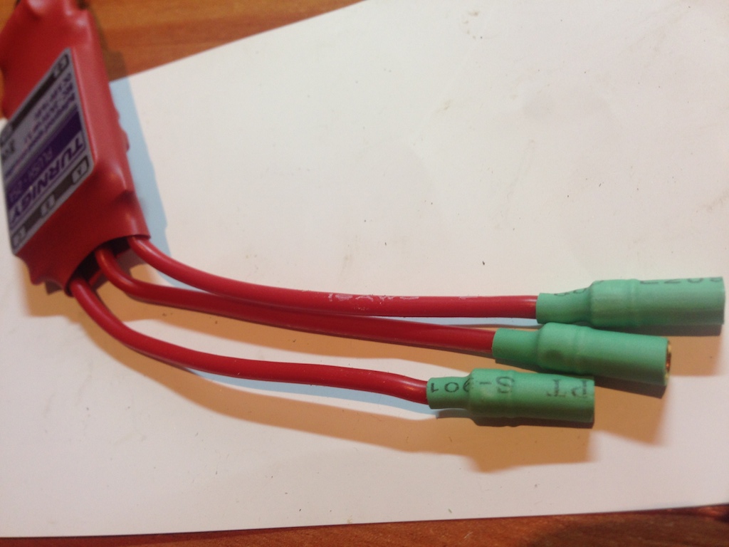
Properly soldered ESC to engine bullet connectors:
Hacky solution using XT60 plug:
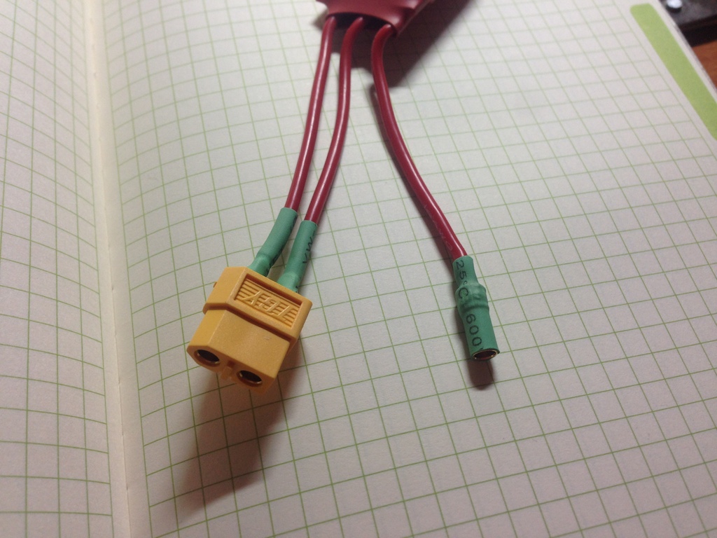
It is absolutely adequate and reliable in terms of connectivity so I’m happy with this for now.
“Power Distribution Plug” is a loud name for another hacky approach. It is used to connect battery to ESCs. 4 x XT60 female plugs are wired to one XT60 male plug:
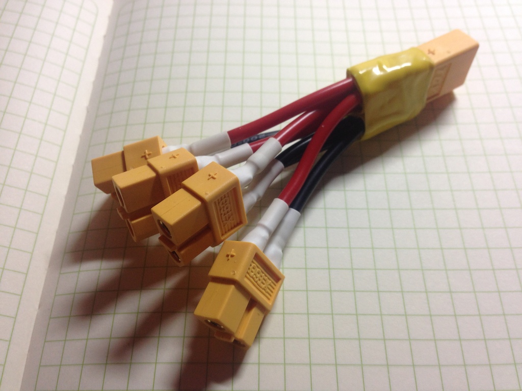 It was not easy to solder 4 x 16 AWG wires together. Have you ever thought how to measure and define wire thikness? It appeared that there is a system called American wire gauge which declares a standard for that.
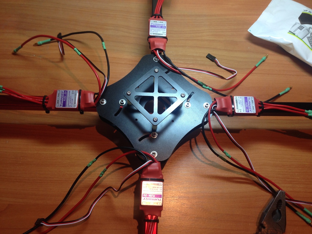
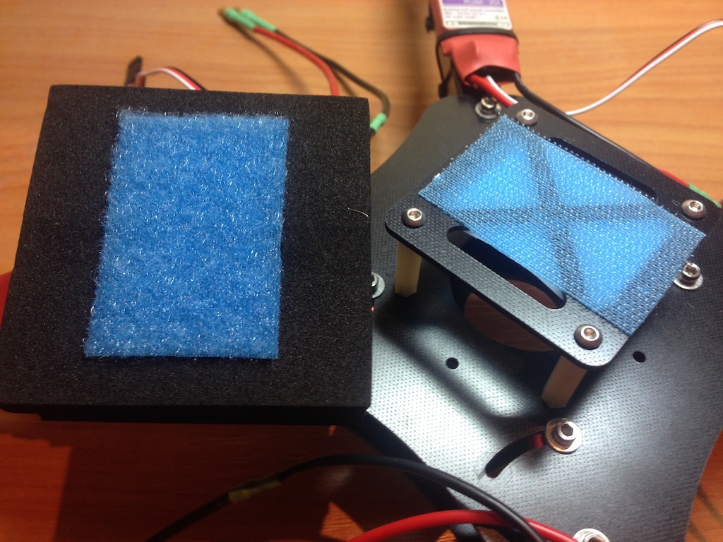
I used cable ties to mount ESCs on frame and velcro tape to mount flight controller box on top. I’m leaving wire mess for now, until I’m sure everything is connected in right order.
ESCs mounted on the frame:
Mounting place for flight controller board:
It took me some time to figure out proper pinout for receiver, since it has only channels labels, like CH1, CH2, etc while on board I have AILeron, RUDder, ELEvation and so on. It is also important not to confuse signal vs ground.
Finally receivers and ESCs are wired to flight controller:
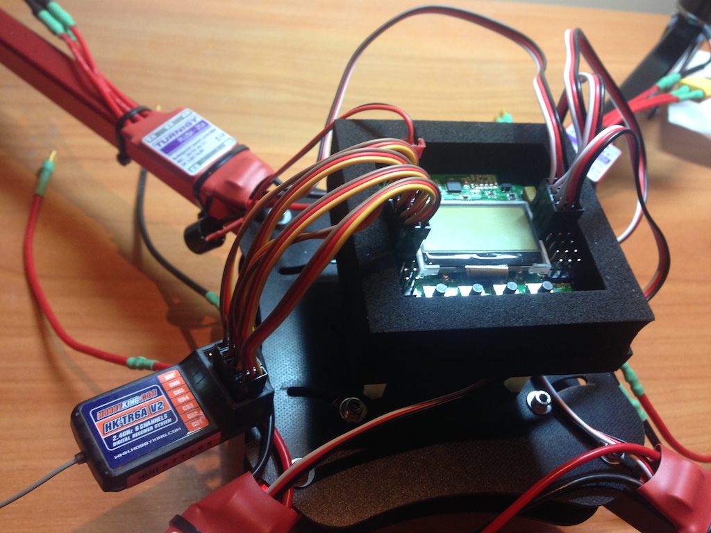
Next step is first power on, which has several important staged, like transmitter and received binding, adjusting receiver signals levels etc, etc.