
Alexander Shchapov


Since last time I finished wiring and now everything is in place. Not much to say about last stage, I think I can just leave couple of photo evidences in here. It’s a log, you know, logs are usually quite verbose and noisy.
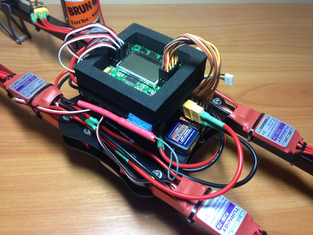
The final wired version looks like this:
At second stage I’ve bounded transmitter with receiver, it is as easy as holding bind button on transmitter and special BAT contacts being short-circuted on receiver.
The one problem I faced at this stage is stick range. For some reason, transmitter returns values for stick travel only at ~80% of requested range. If upper and lower bounds of transmitter stick are set to 100, the highest value I got at maximum physical stick travel is around 80. No idea why. Nevertheless issue was (temprorarily) fixed by setting limits to 120, giving 90-100 actual value seen by flight controller. Assuming limits for controller are set at 100, it recognizes values received from remote as close to full.
Third stage is ESC calibration, the aim of which is to let ESCs know proper upper and lower bounds of throttle stick. ESC typically has several options like start mode, battery type, cut off mode, etc. These options could be configured using special ESC programming card:

Alternatively, sound codes emitted by ESC and remote are used. Calibration stage consists of two steps. At first we’re setting flight controller to ESC calibration mode (in my case it means holding 1 + 4 button while powering on) and then being guided by ESC beeps setting full throttle and idle throttle. Other options could be also set using sound codes and throttle stick. E.g. if you need to set “cut off” option to “soft cut off” you need to wait for 5 beeps after entering configuration menu, then set throttle to full (indicating you entering sub-menu), then wait for 3 beeps and moving throttle down, meaning you selected “soft cut off”. These options and navigation three depend on ESC selected.
At last, I’ve selected motor layout, which, in my case looks like this (it is called Quad X). CW stands for Clockwise, CCW for Counterclockwise seen from top.
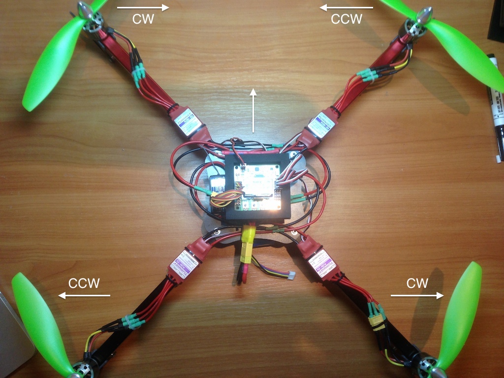
In the result engines are now spinning in a right direction, however I didn’t tried to take the whole thing off in my room, as these four cuties generate quite strong wind even at 10% of throttle!
Next steps are props balancing (yeah, they do need balancing) and PI settings adjustment. I think, props calibration needs to be performed before first flight, while PI calibration can wait (being set to defaults) until the results of first flight.